A customer came to us with a precise requirement.
They needed two synchronized TTL signals:
→ Channel 1: 10 Hz, 100 ns pulse width — the trigger reference → Channel 2: TTL pulse with adjustable delay in the 10–100 ns range relative to Channel 1
The application: driving timing-critical hardware where the delay between two control signals determines the behavior of the downstream circuit. Common in laser driver systems, power converter gate sequencing, and precision measurement triggering.
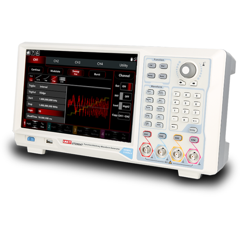
The instrument on the bench: UNI-T UTG9354T — a 4-channel function/arbitrary waveform generator, 350 MHz bandwidth.
The problem they hit was specific and reproducible.
What the customer tried — and why it almost worked
The approach was logical:
- Set Channel 1 as a TTL pulse at 10 Hz, very low duty cycle (short pulse width ≈ 100 ns)
- Route the Channel 1 output to the rear-panel FSK/Trig input
- On Channel 2: select Pulse mode, N-Cycle = 1, high frequency, external trigger source on rising edge
- Adjust Channel 2 frequency and duty cycle to control pulse width
The expectation: Channel 2 fires one pulse each time Channel 1 triggers it, with the pulse width set by the Channel 2 parameters.
The oscilloscope confirmed the synchronization was working — Channel 2 was indeed responding to Channel 1's trigger.
But there was a fixed, unavoidable offset: approximately 250 ns between the Channel 1 edge and the Channel 2 output.
And that offset could not be adjusted.
The customer needed 10–100 ns adjustable delay. What they were getting was a fixed 250 ns — with no control over it.
Why the 250 ns offset exists
This is not a bug. It is a physical reality of how external trigger routing works in a function generator.
When a signal enters the rear-panel trigger input, it passes through:
→ The input protection circuit → The trigger comparator → Digital logic for threshold detection → The internal timing engine → The output DAC and analog output stage
Each stage adds propagation delay. The sum of these delays — typically 200–500 ns depending on instrument architecture — is the trigger response time.
The UTG9354T datasheet specifies a trigger response time of < 1 μs (typical). The 250 ns observed by the customer is well within this specification — it is the instrument behaving exactly as designed.
The problem is not that 250 ns exists. The problem is that the customer needs to control delay in the 10–100 ns range, which is smaller than the minimum propagation delay of the trigger path.
You cannot subtract propagation delay that is already in the signal chain.
The solution: use ChDelay on both channels
The key insight is to stop trying to use the external trigger path as the delay mechanism — and instead use the instrument's internal channel delay (ChDelay) function, which operates before the output stage and is not subject to trigger response time limitations.

Here is the working configuration:
Channel 1 setup: → Waveform: Pulse → Frequency: 10 Hz → Amplitude: TTL levels (0–3.3V or 0–5V depending on load) → Pulse width: 100 ns → ChDelay: set to the desired offset value (e.g., 250 ns to compensate, or any value to establish the timing reference) → Output: ON, Load: HighZ
Channel 2 setup: → Waveform: Pulse → Frequency: 10 Hz (same as Channel 1 — both running from internal clock, phase-locked) → Pulse width: as required → ChDelay: set to Channel 1 delay + desired inter-channel delay → Output: ON
The UTG9354T's ChDelay parameter adjusts the phase relationship between channels referenced to the same internal timebase. Because both channels share the same clock source, the relative timing between them is controlled with nanosecond precision — far better than what is achievable through external trigger routing.
From the screenshot provided during the support case, the instrument was configured with: → CH1: Pulse, 10 MHz, 3.000 Vpp, Offset 0.0 mV, ChDelay 250.0 ns, Duty 50%, REdge 2.0 ns → Output: INV ON, Load: HighZ
By setting ChDelay on Channel 1 as well, the relative timing between the two channels becomes fully adjustable across the nanosecond range — without any dependency on external trigger response time.
The adjustable delay range
With ChDelay controlling the inter-channel timing, the effective delay range is:
→ Minimum: limited by the instrument's ChDelay resolution — typically 100 ps steps on the UTG9354T → Maximum: up to one full period of the waveform
For a 10 Hz signal (100 ms period), the full delay range is 0 to 100 ms.
For the customer's requirement of 10–100 ns adjustable delay: fully achievable. The minimum step size is well below 10 ns, and the range extends far beyond 100 ns.
Why this approach is more reliable than external triggering for precision timing
External trigger → output path involves analog and digital signal processing with variable propagation delay:
→ Temperature dependence: trigger comparator threshold voltage shifts with temperature, changing the precise moment of trigger detection → Input signal slew rate sensitivity: a slow-rising trigger edge produces later detection than a fast edge → Jitter: each trigger event has slightly different propagation delay, contributing cycle-to-cycle jitter to the output
Internal ChDelay uses the instrument's phase accumulator — a purely digital operation synchronized to the master clock. The delay is deterministic, temperature-stable, and jitter is limited only by the master oscillator quality.
For timing requirements in the 10–100 ns range, the difference between these two approaches is measurable and significant.
When external trigger is still the right choice
The internal ChDelay approach assumes both channels are running at the same frequency from the same internal clock.
External triggering remains necessary when: → The trigger source is an external event (e.g., a sensor output, a DUT response, a hardware interrupt) rather than an internally generated reference → The two signals need to have different base frequencies with a defined phase relationship → The application requires single-shot pulse generation on demand from an external source
In those cases, the 250 ns (or similar) trigger response time is unavoidable, and the system design must accommodate it — either by pre-compensating with a known fixed offset, or by choosing an instrument with a lower trigger response time specification.
For applications where both signals can share a common internal timebase — which covers the majority of delay generator use cases in lab and production test environments — ChDelay is the correct and more precise tool.
Summary: the two-line solution
The customer's requirement was met with a configuration change that took less than two minutes to implement:
→ Remove the external trigger connection from the rear panel → Set both channels to the same frequency, internal clock → Use ChDelay on each channel to set the absolute timing of each output → Adjust the difference between ChDelay values to control inter-channel delay
The 250 ns fixed offset disappeared. The 10–100 ns adjustable delay requirement was satisfied. The instrument that "couldn't do it" turned out to be fully capable — with the right operating mode.
Technical support case documented with customer permission. Customer and company details anonymized.